Arch 3 – Saying Hello With LED
Hello World
In embedded systems, a common theme of “hello world” applications is blinking an LED. Despite being a simple task, it is very effective in walking us through the hardware setup, development environments and the essential language syntax.
In the last episode, we illustrated the basic concepts of object-oriented design (OOD) using everyday examples, such as vehicles, sedans, SUVs, car models and a car inventory. In this episode, we enter the embedded world and attempt to use OOD to design a hardware-based feature that you may actually design for your projects. Rather than just blinking an LED, we will control an LED to show arbitrary patterns.
OOD and UML
Our first task is to design a set of classes to represent an LED pattern. As we will be talking about objects, their relationships and interactions, we need an effective way to describe them. Natural language can quickly become clumsy and imprecise. UML, Unified Modeling Language, is an attempt to offer a common graphical language to solve this problem.
You can get the UML 2.5 Specification from its official website: https://www.omg.org/spec/UML/2.5.1/PDF
UML by itself does not provide any means of implementation. There are many tools, both commercial and open-source, that help translate graphical UML models to executable code. Quantum Platform (QP) is one of such tools and later on we will see how QP supports object-oriented design of real-time embedded systems.
Among different kinds of UML diagrams, the following three are commonly used for embedded system design. We will start with class diagrams in this episode.
- Class diagrams
- Sequence diagrams
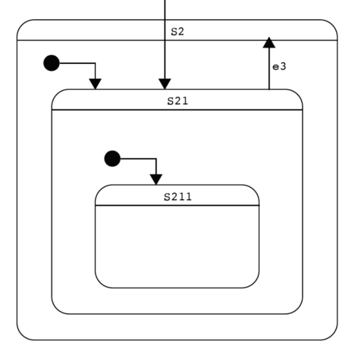
- Statecharts
Class Diagrams
A class diagram shows the static structure of a class. It reveals what data members and member functions (or methods) a class contains, and the visibility of its members (public, protected or private). The public member functions of a class are collectively known as its API (application programming interface).
The type of a data member or the return type of a member function is shown after the “:” sign following the name of a member. It can be a built-in type such as uint32_t or a custom class type.
Data members are listed in the upper compartment while member functions are listed in the lower one. Visibility is marked by a “+”, “#” or “-” sign at the front of each member:
- + public member It can be accessed in both member and non-member functions of this class.
- # protect member It can only be accessed by member functions of this class, its derived classes or by its friends.
- – private member It can only be accessed by member functions of this class, or by its friends.
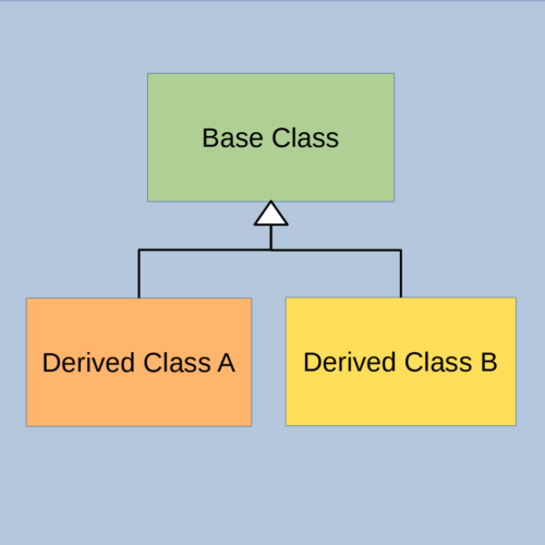
A class diagram also shows the static relationship between classes such as composition (has-a) or inheritance (is-a). Composition is denoted by a line with a solid diamond attached to the containing class. Inheritance is denoted by a line with a hollow triangle attached to the base class.
A class diagram, however, does not show the dynamic behaviors of a class, e.g. how its data members are used or what its member functions do, nor does it show the dynamic interactions among classes.
What is an LED Pattern?
Equipped with the graphical tool, class diagrams, to capture our design ideas, we are now ready to think about these questions:
- What is an LED pattern make of? In other words, what will an LED pattern be decomposed into?
- If we want multiple LED patterns, what do we need to contain them or group them together?
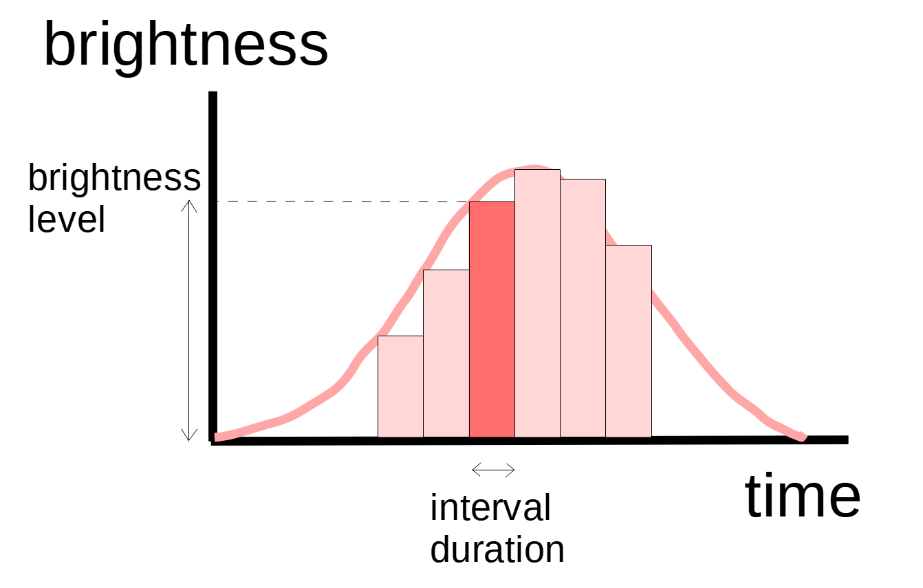
Answering these questions will guide us through the design process. To help answer the first question, let’s draw a diagram to illustrate what an LED pattern is. To keep it simple, we start our design for a single-color LED.
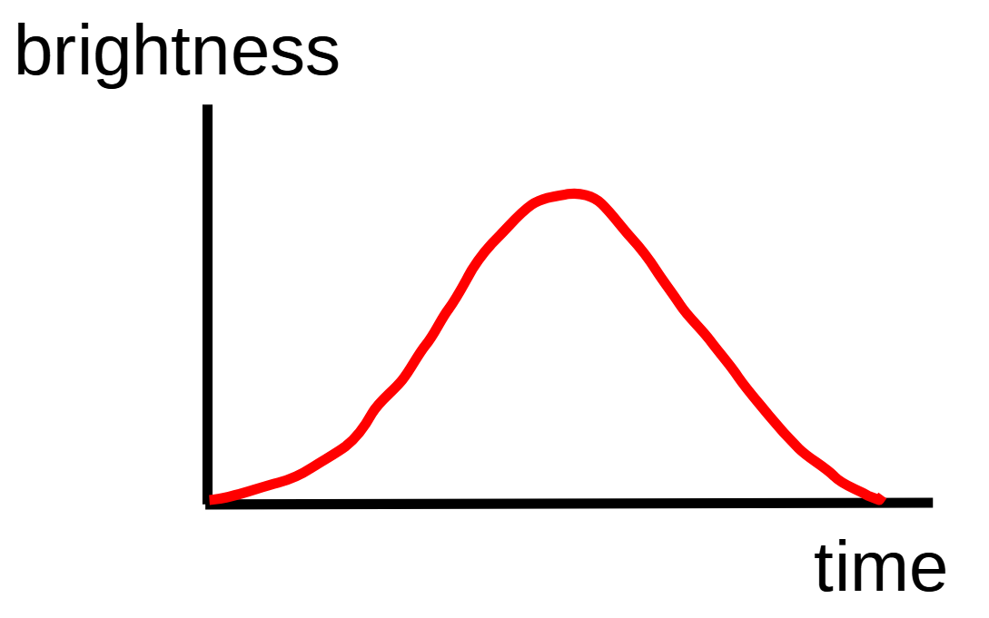
As shown in the diagram above, an LED pattern is the variation of brightness over time. The bell-shaped curve above corresponds to a breathing pattern. One way to represent an arbitrary waveform with a computer is to use sampling and quantization. We sample the brightness periodically with the duration of each sampling interval called the interval duration. We approximate the brightness of each interval with an integer of a certain range. For example, we can represent the brightness level with an 8-bit integer giving a range of 0 – 255 (256 levels). To get a higher resolution, we are going to represent the brightness with a permil/per mille level (0 – 1000) using a 16-bit integer, where 0 means off and 1000 means full brightness.
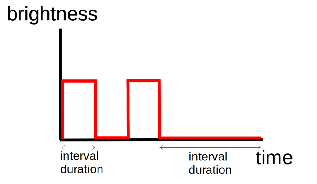
Here is another LED pattern showing two short blinks in each cycle:
LED Pattern Classes
Following the analysis above, we observe a number of composition relationships:
- An LED pattern set contains one or more LED patterns.
- An LED pattern contains one of more intervals.
- Each interval contains an interval duration and a brightness level.
In other words we are saying an LED pattern set has a collection of LED patterns, each of which has a sequence of intervals, which in turn has a brightness level and an associated duration.
What we are designing is more than just LED patterns, but can be generalized to any patterns that controls hardware peripherals such as motors. Rather than calling them LED patterns, we call hem GPIO patterns. In the following class diagram below, we show the three main classes of GpioPatternSet, GpioPattern and GpioInterval, and how they relate to one another via composition.
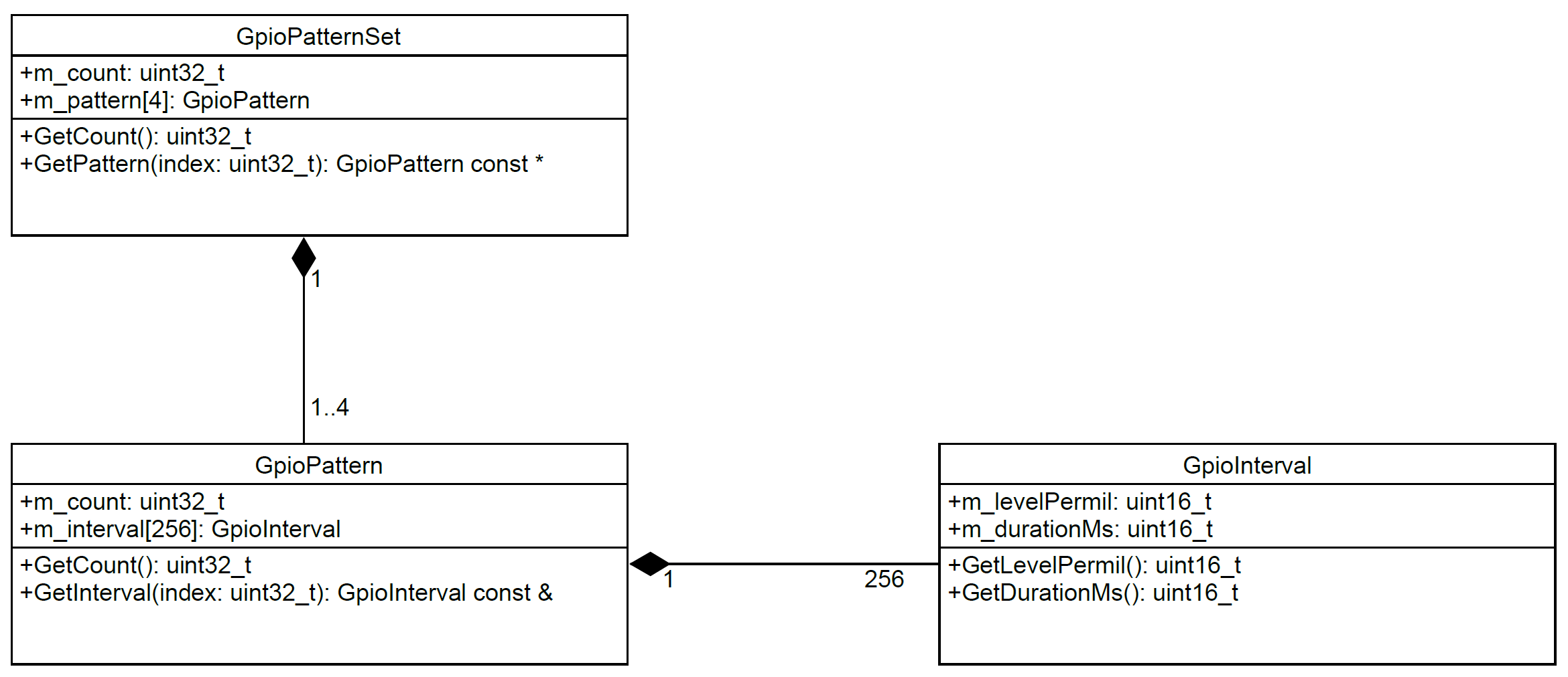
With the classes and their relationships designed, coding is merely a mechanical process to translate the class diagram into C++ constructs:
class GpioInterval {
public:
    uint16_t m_levelPermil;     // Brightness level 0-1000.
    uint16_t m_durationMs;      // Duration in millisecond.

    uint16_t GetLevelPermil() const { return m_levelPermil; }
    uint16_t GetDurationMs() const { return m_durationMs; }
};
class GpioPattern {
public:
    enum {
        COUNT = 256
    };
    uint32_t m_count;                // Number of intervals in use.
    GpioInterval m_interval[COUNT];   // Array of intervals. Used ones start from index 0.

    // Must perform range check. Assert if invalid.
    uint32_t GetCount() const {
        return m_count;
    }
    GpioInterval const &GetInterval(uint32_t index) const {
        GPIO_PATTERN_ASSERT(index < m_count);
        return m_interval[index];
    }
};
class GpioPatternSet {
public:
    enum {
        COUNT = 4                   // Maximum number of patterns supported.
    };
    uint32_t m_count;               // Number of patterns in use.
    GpioPattern m_pattern[COUNT];   // Array of patterns. Used ones start from index 0.

    uint32_t GetCount() const {
        return m_count;
    }
    GpioPattern const *GetPattern(uint32_t index) const {
        if (index < m_count) {
            return &m_pattern[index];
        }
        return NULL;
    }
};
To test the classes, we define a constant GpioPatternSet object named TEST_GPIO_PATTERN_SET using aggregate initialization. The form of initialization allows us to see all the parameters together and is very convenient to update them when needed.
GpioPatternSet const TEST_GPIO_PATTERN_SET = {
    2,  // No. of patterns.
    {
        // Pattern 0.
        {
            21, // No. of intervals.
            {
                {10,50},  {20,50},  {30,50},  {50,50},  {70,50},
                {100,50}, {200,50}, {400,50}, {500,50}, {900,50},   // Ramps up.
                {900, 2000},                                        // Constant high.
                {900,50}, {500,50}, {400,50}, {200,50}, {100,50},
                {70,50},  {50,50},  {30,50},  {20,50},  {10,50},    // Ramps down.
            }
        },
        // Pattern 1.
        {
            4, // No. of intervals.
            {
                {500,200}, {0, 200}, {500, 200}, {0, 1000}          // Two short blinks.
            }
        }
    }
};
Next we demonstrate how to display one of the GPIO/LED patterns identified by the integer patternIdx (which in our example can be 0 or 1). The inner for-loop iterates all the intervals contained by the selected pattern, and the outer for-loop repeats the pattern 5 times. ConfigPwm() is a helper function to output a PWM (pulse-width modulation) signal on a GPIO pin, which controls the intensity of an LED or speed of a motor. Delay() is a helper function to pause the program execution for some time, which in the case of LED control allows its intensity to stay constant for the duration of an interval.
GpioPattern const *pattern = TEST_GPIO_PATTERN_SET.GetPattern(patternIdx);
if (pattern) {
    for (uint32_t i = 0; i < 5; i++) {
        for (uint32_t idx = 0; idx < pattern->GetCount(); idx++) {
            GpioInterval const &interval = pattern->GetInterval(idx);
            ConfigPwm(interval.GetLevelPermil());
            Delay(interval.GetDurationMs());
        }
    }
} else {
    console.Print("Invalid pattern %lu\n\r", patternIdx);
}
Looking Ahead
In this episode, we developed some basic classes to represent LED patterns, and a simple application to demonstrate how to use them. However using a loop with Delay() or sleep() is not the right way to build robust and scalable software. In the coming episodes, we will explore some important software architectural patterns and revisit the topic of LED patterns.
We will build on top of these basic classes to go beyond a single-color LED. We will learn how to control multiple RGB LEDs with each showing its own patterns! Stay tuned.