Arch 4 – Finite State Machines
Finite State Machines
Before we introduce the powerful concept of hierarchical state machines (HSM), let’s review a related concept of finite state machines (FSM) which is the foundation of the theory of computation. It is often used as a mathematical model to study formal systems. It is very popular in telecommunication and aerospace industries to design protocol stacks and ensure system reliability. Apart from that, it is surprisingly rarely used even in (UI development where the concept of state is dominant.
Someone might say a state machine adds complexity, as a traditional state diagram can look quite complicated with numerous states and transitions interwoven like a nest. It’s both true and false.
It is true that a traditional state diagram (flat) due to its infamous state explosion problem fails to express any realistic design in a neat way. Later we will see how statecharts (hierarchical) solve this problem with some innovative and intuitive concepts.
It is false that using state machines increases the complexity of your design. In many cases, complexity is inherent in the system itself, as it is required to handle all possible scenarios. Even when you are not using a state machine explicitly, you may just be implementing an implicit state machine with flags and if-else statements without realizing it. An explicit state machine simply helps reveal the inherent complexity so that we can visualize it, discuss it and reason about it. When you find your state diagram over-complicated, you will likely find a way to simplify it and hence yield a simpler design.
FSM Notation
What is a finite state machine? Most textbook on the theory of computation would give you a formal definition of FSM in the first few chapters. It is expressed as a tuple of a finite set of states (S), a finite set of events (E) and a transition function (S x E -> S).
In plain programming terms, you have an enumeration of State and an enumeration of Event. State lists all the possible situations or conditions that your software component is concerned of when reacting to an event. Event lists all the different types of signals that your software component may receive, upon which some actions may be taken along with a possible state change (called transition).
This is a simple example:
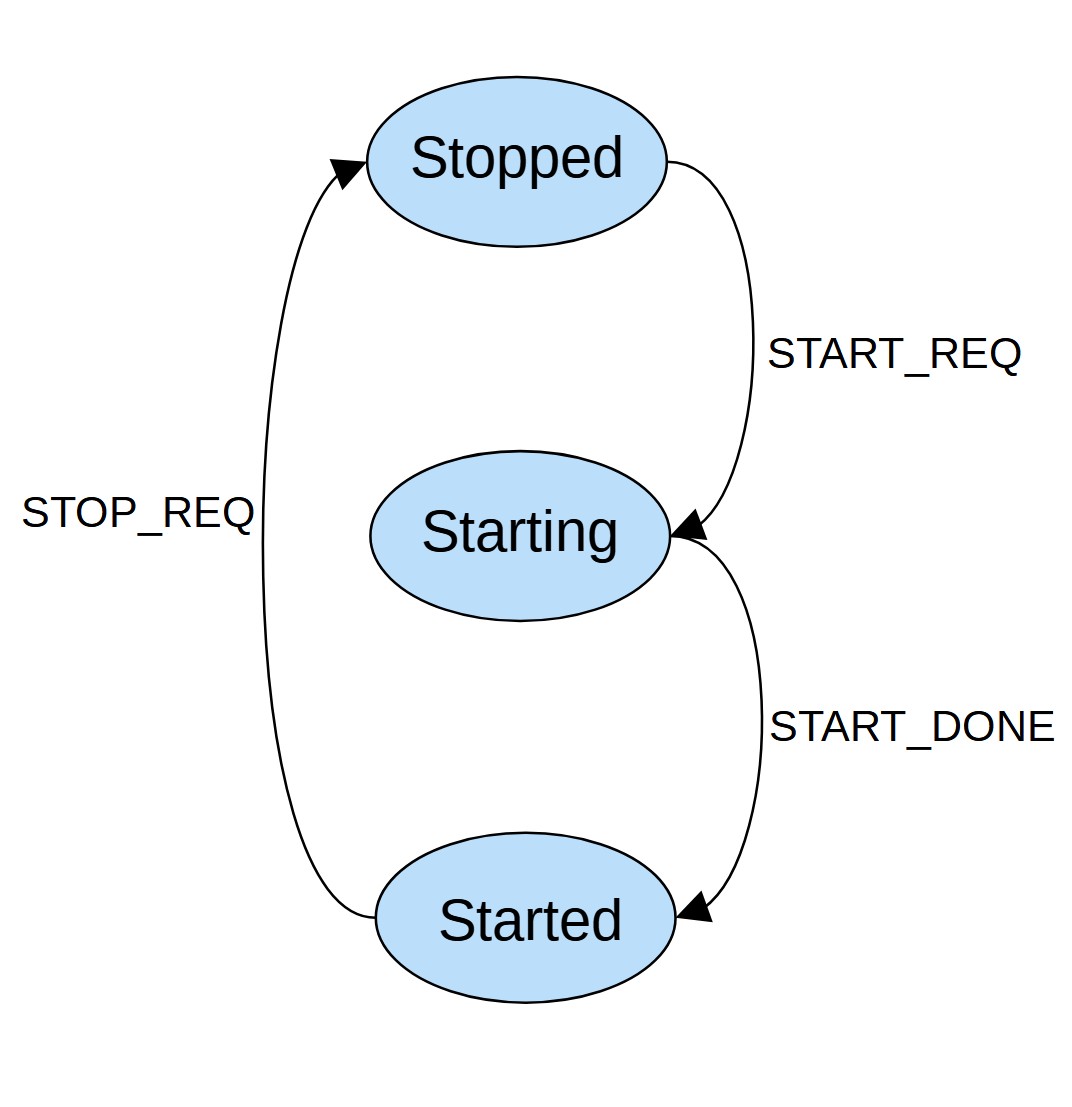
enum State {
    STOPPED,
    STARTING,
    STARTED
};
enum Event {
    START_REQ,
    START_DONE,
    STOP_REQ
};
The corresponding state diagram is shown below. There is no standard convention of a traditional state diagram. Typically we use a circle or eclipse to represent a state, a label for an event and a directed line for a transition.
Once a state diagram is drawn, software developers have a few options to implement it in programming language like C/C++. We will look at some approaches in the next section.
Philosophy
Before moving on let’s pause for a moment to reflect on what is special about state. State exists in our software without our thinking about it. Ultimately what software does is to take some actions upon inputs (events) it receives. The actions it takes depend not only on the current input but also on the current condition or state of the system (which is affected by the history of past inputs). The question is: How do we represent such conditions or states in software?
At the bottom layer it is bits of zeros and ones. At a higher level, we abstract groups of bits into bytes or words, and eventually into variables. One simple approach is to just represent states with variables. Upon an input, our software determines what actions to take based on the current values of some variables (could be one or a bunch).
This sounds familiar to us, since we know from our software experiences that programming involves (i) defining variables and (ii) use conditional constructs like if-else and switch-case together with logical operators like &&and|| to check on some combinations of variables. The problem is that just a single 32-bit variable can store 232 possible values or states. If you combine multiple of them together in a logical expression, the total number of possible combinations or cases to consider could be astronomical. Have you seen conditional statement like this before?
    if ((battLevel >= THRESHOLD_LOW) && (battLevel < THRESHOLD_HIGH) &&
        (temperature >= TEMP_LOW) && (temperature < TEMP_HIGH) &&
        usbHal.IsPluggedIn() && (!dcCharger.IsPluggedIn() || usbChargeOverride) &&
        (usbHal.ReadRegister(OVER_CURRENT_ERROR_COUNT) < 3) &&
        (!chargingStarted) {
        usbHal.StartCharging(CONSTANT_CURRENT_MODE);
        chargingStarted = true;
        ....
    }
When looking at a particular conditional statement individually, despite being complex, we might still understand what will happen under certain specific conditions. In the example above, we could understand under what conditions would USB charging be started. However when doing that we are only considering one facet of the total behaviors. We cannot tell what would happen when the conditions above are evaluated to false. Either the design is incomplete if it hasn’t considered all possible cases, or those cases are scattered or buried around the source code which makes it very hard to reveal them to form a whole picture.
Fundamentally it is a problem of abstraction. Out of the possible (232)N possible combinations of values ofN integer variables, only a handful are meaningful to us. Defining states allows us to think at a higher level of abstraction, reasoning about a relatively small space of discrete states than a much larger space of continuous variables.
A state machine makes it very clear and explicit when a state is changed and what it is changed to. If we use a combination of variables or flags to represent state implicitly, we need to be concerned of when each one of those variables or flags is set, cleared and checked. As they tend to be scattered in the source code across multiple files, it can be a daunting task especially when the author is somebody else.
Traditional Implementation
The book Pracitical Statecharts in C/C++ by Miro Samek (PSiCC) gives an excellent presentation of traditional state machine implementations. See Chapter 3 Standard State Machine Implementations of PSiCC for details. This is a summary of those approaches.
Double-switch
Use the first level of switch-case construct to check states and the second level to check for events. A simplified example is shown below:
void Dispatch(Event event) {
    switch (currentState) {
        case STOPPED:  StoppedStateHandler(event); break;
        case STARTING: StartingStateHandler(event); break;
        case STARTED:  StartedStateHandler(event); break;
    }
}
void StoppedStateHandler(Event event) {
    switch(event) {
        case START_REQ:
            DoStart();
            currentState = STARTING;
            break;
        case START_DONE:
            LOG("Unexpected event START_DONE in state STOPPED.");
            break;
        case STOP_REQ:
            LOG("Ignored event STOP_REQ in state STOPPED.");
            break;
    }
}
State Table
Rather than having state and event checks in explicit switch-case statements, we encode the businesslogic in a constant data table so the code itself becomes simpler and more generic. The underlying idea is similar to the double-switch approach. There are a few variations of how much information is encoded in the table. Some approaches encode just the handler function for each combination of the current state and events while others include a guard condition and the next state. The example below illustrates the minimal approach:
typedef void (*Handler)(Event event);
void StoppedStateStartReq(Event event) {
    DoStart();
    currentState = STARTING;
}
void UnexpectedEvent(Event event) {
    LOG("Unexpected event %d in state %d", event, currentState);
}
void IgnoredEvent(Event event) {
    LOG("Ignored event %d in state %d", event, currentState);
}
...
const Handler table[STATE_COUNT][EVENT_COUNT] = {
    { StoppedStateStartReq, UnexpectedEvent,        IgnoredEvent        },
    { IgnoredEvent,         StartingStateStartDone, UnexpectedEvent     },
    { IgnoredEvent,         UnexpectedEvent,        StartedStateStopReq }
};
void Dispatch(Event event) {
    table[currentState][event](event);
}
State Pattern
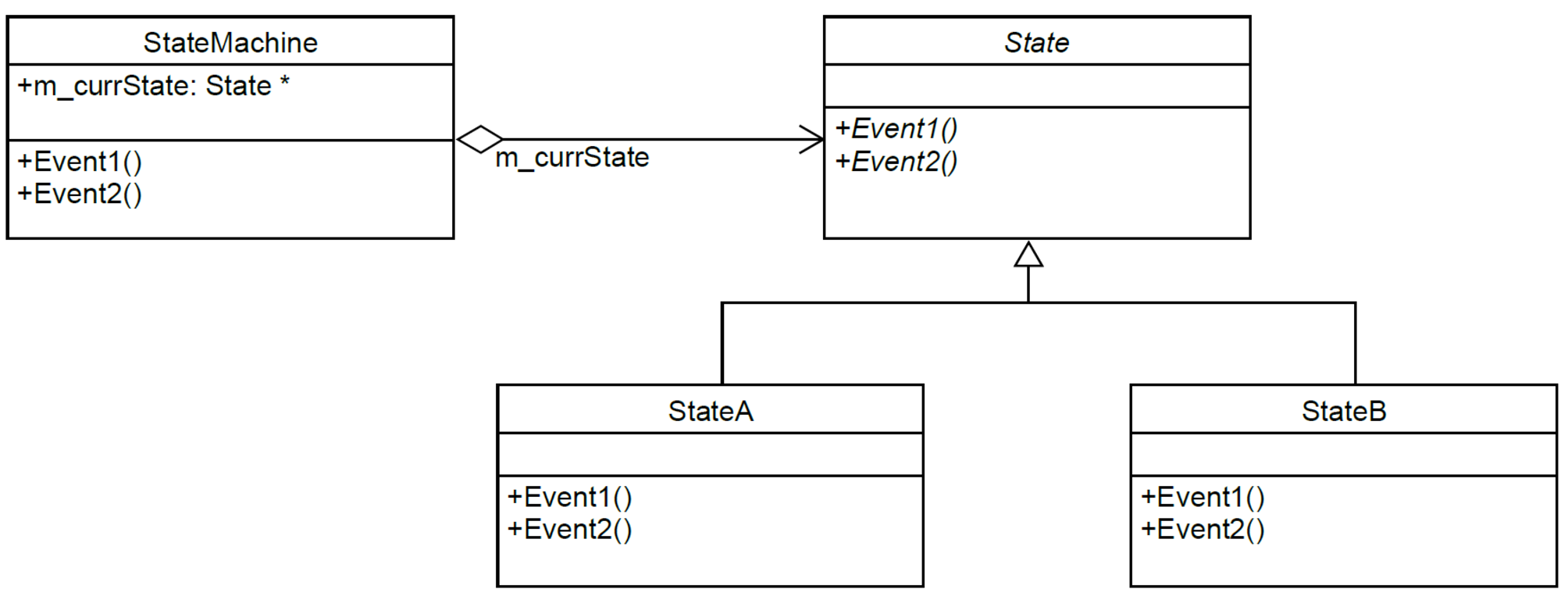
This approach comes from the State Pattern in the classic book on object-oriented design patterns, titled Design Patterns: Elements of Reusable Object-Oriented Software byErich Gamma, Richard Helm, Ralph Johnson and John Vlissides (Addison-Wesley, 1994). Each state is represented by a subclass derived from a common base class for all states. Each event is handled by a particular virtual function declared in the base class, allowing each individual state to customize its handling of the event by overriding the virtual function in its own subclass.
A pointer to the base class points to the subclass object representing the current state. An event is dispatched to the current state by invoking the corresponding virtual function via that base class pointer. This is an elegant approach, but due to the lack of support for state hierarchy, it is not really scalable to real-life projects.