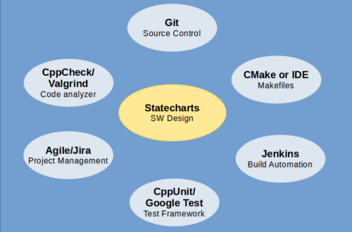
Arch 5 – Hierarchical State Machines
That was an account of how an air force pilot, seeing a statechart for the first time, could spot an error in the behaviors of a fighter jet:
“If an outsider could come in, just like that, and be able to grasp something that was pretty complicated but without being exposed to the technical details of the language or the approach, then maybe we are on the right track.” from Statecharts in the Making: A Personal Account by David Harel (ACM Communications, March 2009).
This suggests that the statechart notation is very expressive and at the same time very intuitive. It can describe complicated behaviors precisely, yet it can be understood by someone without computing background.
Statechart Notations
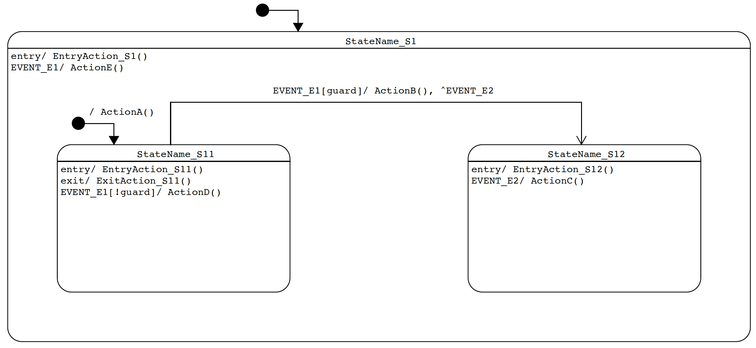
Our journey in statecharts begins with a simple and hypothetical statechart below. It does not do anything meaningful yet illustrates many important notation and concepts. In subsequent sections, we will gradually introduce more advanced concepts.
State
A state is represented by a round-cornered rectangle with its name denoted in the upper compartment.
A state may contain other states. The containing state is called a superstate or composite state. The contained state is called a substate or nested state. There can be multiple levels of nesting. This is like the superclass and subclass relationship in object-oriented programming (OOP).
Due to the hierarchy of state composition, this kind of state machine is called hierarchical state machine, or simply HSM. We will refer to this acronym a lot, so it is important to remember what it means.
When the system is in StateName_S1, it must also be in either StateName_S11 or StateName_S12 but not both. StateName_S1 is also called an OR-state. Whenever the system is in an OR-state, the system must also be in exactly one of its substates. Later we will see another kind of composite state called an AND-state.
The default initial state is indicated by a dark solid circle/dot called the initial pseudo-state. The transition from it points to the default state to enter at each nesting level. In our example, the system enters StateName_S1 followed by entering StateName_S11 by default (i.e. after initialization).
In each state there can be optional entry actions and exit actions, labeled as:
entry/ action_list
exit/ action_list
See the next section for an explanation of action_list. Essentially entry actions are the activities to perform every time when a state is entered, regardless to which transition is taken to enter the state. Similarly exit actions are the activities to perform every time when a state is exited. This is one of the core features of statecharts.
Transition
A transition (non-internal) is a directed line from a source state to a target state triggered by an occurrence of an event labeled in the following format:
EVENT_NAME[guard_condition]/ action_listEVENT_NAME identifies the type of the triggering event, such as EVENT_E1, or more concretely START_REQ and START_DONE in our previous episode. See the next section on a special kind of transitions called internal transitions.
guard_condition is a logical expression determining if a transition is enabled. A transition is only enabled if the triggering event arrives and the associated guard condition is evaluated to true. Examples include:
[retryCount < 3]
[temperature >= 0 && temperature < 90]
Guard conditions uses extended state variables which are member variables of state machine objects. They are very useful in augmenting the discrete states but nonetheless they are what state machines are trying to replace, and therefore we need to find a sweet spot and not overuse them.
action_list is a comma-separated list of activities to perform when the transition is triggered or fired. A transition is triggered when it is enabled and selected. We mentioned above that the guard_condition determines if a transition is enabled. Later on we will discuss how a transition gets selected when there is a conflict among multiple enabled transitions (conflict resolution).
An action_list can be empty, meaning that there are no activities to accompany the transition. Otherwise it may contain a combination of (i) actual functions to be called, (2) events to be posted (via Send()or Raise()), or (3) free-formed descriptions. Examples of action_list include:
/ gpioHal.SetPin(LED1), motorDriver.Forward(speed)
/ turn on LED1, forward motor at speed
/ retryCount++, Raise(RETRY)
In the above example, RETRY is called a reminder (or internal) event. It is posted to itself to trigger a follow-up transition. There are different favors regarding how an event is posted, which are related to the underlying queuing model. We will discuss the differences between Send() and Raise() in later episodes on framework design.
Initial transition is a directed line from an initial pseudo-state (dark solid dot) to the default state to enter. By nature of being default, there shouldn’t be an EVENT_NAME or [guard_condition] in the label. (There is an exception. If there is a choice point, there can be a [guard_condition] on each branch coming out of the choice point.)
Internal Transition
An internal transition is a transition without state change (a.k.a. a targetless transition). It remains in the same state without even exiting and re-entering the state, and hence no associated exit and entry actions are performed. Since there is no state change, there is no need for a directed line. Only a label is needed, which is placed inside the state rectangle at the top-left corner. Think about how this is different from a transition with identical source and the target state.
Internal transitions can be viewed as the activities to perform while remaining in a certain state. Often these activities represent the main features of a system when it is in a stable state, such as transferring data, handling periodic timeout events, etc. Together with the transition lines, they allow the complete system behaviors to be represented, which is not possible with traditional state diagrams using simple circles and arcs.
Statechart Rules
State Hierarchy and Transition Triggering
In a statechart, states are organized in a tree structure. Starting from the topmost root state, each state may contain substates. The relationship between a substate and its containing states (superstates) is similar to that between a subclass and its superclasses, which is an “is-a” relationship. In our example, if the system is in StateName_S11 we say it is also in StateName_S1.
When an event arrives, it first determines the set of enabled transitions in the current leaf state (most nested) and all of its superstates. Recall that a transition is enabled when its guard condition, if any, is evaluated to true.
There is a conflict if there are more than one enabled transitions in the set. The system attempts to resolve the conflict by selecting one transition out of the set with the priority given to the most nested state. The conflict cannot be resolved if there are more than one enabled transitions in the same state, and the statechart is deemed malformed. This is similar to how overriding functions are resolved in the order from the most derived class to the base class in OOP.
In the example statechart above, we have made the following observations.
When EVENT_E1 arrives in StateName_S11,
- if guard is true, ActionB() will be called and the system transitions to StateName_S12.
- if guard is false, ActionD() will be called and the system stays in the same state.
- ActionE() in the superstate will never be called.
When EVENT_E2 arrives in StateName_S11, there are no enabled transitions and the event will be discarded.
When EVENT_E2 arrives in StateName_S12, ActionC() will be called.
When EVENT_E1 arrives in StateName_S12, ActionE() in the superstate will be called.
Note – There is a subtle difference between a guard condition and an if statement in the action list. In the former case, if a guard condition is false the transition is not enabled, and therefore will not be considered for selection. In the latter case, no matter whether the if-condition is true or false the transition overrides any other enabled transitions in its parent states.
State Exits and Entries in a Transition
Let’s define some terminology for this discussion:
- Current state – The leaf (most nested) state the system is in at the moment.
- Transition source – The originating state of a transition line.
- Transition target – The terminating state of a transition line.
- Final state – The new leaf state after transition.
A transition source can be the same as the current state, or a parent of the current state. A final state can be the same as a transition target, or a child of the transition target.
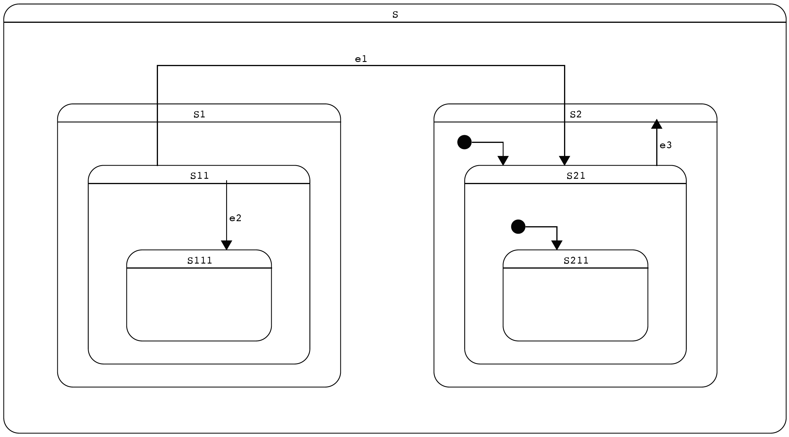
For example, when e1 arrives in S111, the transition source (S11) is the parent of the current state (S111). The transition target (S21) is the parent of the final state (S211) due to initial transition.
During a state transition, states will be exited and entered, and the corresponding exit and entry actions will be automatically performed. The sequence of actions can be divided into the following three main steps:
- Exit actions from the current state up to but not including the transition source. When both are the same there will be no actions in this step.
- Exit actions from the transition source up to but not including the lowest (least) common ancestor (LCA), followed by entry actions from there into the transition target. When the transition source is the same as the transition target, unless it is an internal transition, the source/target state is still exited and re-entered. For internal transitions, there will be no actions in this step.
- Entry actions from but not including the transition target into the final state. When the transition target is the same as the final state there will be no actions in this step; otherwise the system will follow the initial transitions repeatedly until reaching the final state.
Special Cases
We will be using Quantum Platform (QP) for our statechart implementation in C++. Regarding the transition rule #2 above, there are a couple special cases in its implementation:
- If the transition source is a parent of the transition target (e2), the transition source is not exited and re-entered.
- If the transition source is a substate of the transition target (e3), the transition target is not exited and re-entered.
Note that there could be variations among different statechart implementations or libraries. Please check out the following references for details.
Ref. 1 – See Figure 2.10 on page 81 of PSiCC by Miro Samek for details (Book: Practical UML Statecharts in C/C++, 2nd Ed. (state machine.com)).
Ref. 2 – See Section 14.2.3.8.1 Transition kinds relative to source and Section 14.2.4.9 TransitionKind of UML 2.5.1 specification available at About the Unified Modeling Language Specification Version 2.5.1 (omg.org).
Ref. 3 – Also see SCXML spec at State Chart XML (SCXML): State Machine Notation for Control Abstraction (w3.org). There is a notion of transitions with type of “internal”, which are very similar to local transitions in UML 2.5.1:
“The behavior of transitions with ‘type’ of “internal” is identical, except in the case of a transition whose source state is a compound state and whose target(s) is a descendant of the source. In such a case, an internal transition will not exit and re-enter its source state, while an external one will, as shown in the example below.”
Though the rules may sound complicated, they are very intuitive. Try to follow the transitions in our example above (e1, e2 and e3) and check if the results obtained by the rules match your intuition.