Arch 7 – Asynchronous vs Synchronous Design
Having learned about the notation and rules of statecharts, as well as how to implement statecharts with the QP framework, we are now ready to take on a real-life design problem with statecharts.
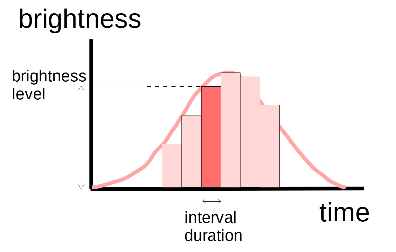
In a previous episode (link), we implemented a simple LED pattern generator using a typical synchronous approach, which calls blocking sleep/delay functions when it needs to wait for some time and uses for-loops when it needs to do something repeatedly. The following is the pseudo-code of the synchronous algorithm, and the diagram below illustrates one cycle of the pattern.
for (5 cycles) {
    for (number of intervals in the LED pattern) {
        ConfigPWM(interval brightness)
        Delay(interval duration)
    }
}
Synchronous Approach – Simple but Problematic
The synchronous approach is definitely very neat and simple. It really can’t get simpler than that, can it? Its sequential logic follows directly from our common thought process, and employs constructs we are most familiar with. Loops and function calls, including the ever-popular sleep(), are what we were taught when we started learning programming.
What is the problem? The algorithm above is simple because it only handles the nominal case, or the happy path as we call it. This is just one of the many use cases or scenarios that this component needs to handle. We could certainly augment it with additional flags and conditional statements to handle the corner cases. However this ad hoc approach could easily result in a fragmented and incomplete design.
So what are the possible corner cases for our LED pattern generator? To answer the question, we just need to think about what may happen when the component is blocked, which in this case is in the call to Delay(). Here are some examples:
- A user wants to show a different LED pattern.
- A user wants to restart the same LED pattern.
- A user wants to stop the LED pattern.
For the sake of discussion, let’s assume for each of the above cases, we want the system to respond to a user input as quickly as possible. For example, the system would be able to switch to a different pattern immediately even when it is busy showing a current pattern.
The lack of responsiveness is the Achilles’ heel of the synchronous design paradigm. When a component is blocked, it becomes unresponsive to any inputs (e.g. a user input or hardware signal) until what it is waiting for has become ready/available or a timeout has expired. Some operating systems supports interruptible blocking functions, but that is more of a workaround than a general fix of the root cause. It puts a burden on the application to handle one more special case of an interrupted system call, and it would probably require additional flags and if-else logic to handle this extra special case.
Asynchronous Approach – Responsive and Robust
The fundamental fix of the responsiveness issue is to get rid of points at which a component is blocked and hence unresponsive to changes in its environment (i.e. events). This is the most general case compared to incremental fixes we may add to the synchronous approach, such as shortening the sleep duration or timeout period of blocking calls in order to increase the polling frequency.
In the end, we only need a single blocking point in each component which blocks on an event queue when the queue is empty. It is OK to block then since there is nothing for the component to handle. When processing events, the component does not block and each function call returns quickly. In case it needs to wait for the completion of an operation or other notifications, it gets informed via events.
There are two critical facilities to make this asynchronous approach manageable. The first is an event framework providing a universal mechanism for asynchronous communications. This avoids the drawbacks of the popular callback mechanism which often leads to concurrency issues or hard-to-maintain nested callbacks. The second is a state machine framework. Here we are taking about formal well-defined states rather than a general blob of context variables. State is crucial since a component must precisely determine how to react to an event based on its current situation which may be changing all the time. In order to keep track of complex real-world situations, we need to support hierarchy in our state machines, and hence hierarchical state machines (HSMs).
Due to its non-blocking nature, an asynchronous component is extremely responsive to events coming from its environment, such as another component, a system timer or an interrupt service routine (ISR). Through the use of hierarchical states, a component is designed right from the start how all events are handled in all possible situations, resulting in a very robust system.
Sequence Diagrams
While class diagrams do not show dynamic interactions among classes, sequence diagrams come to the rescue. A sequence diagram represents each object participating in a scenario with a lifeline which is a vertical dashed line coming down from a rectangle showing its name. It uses a horizontal line with a solid arrowhead to show a synchronous function-call from one object to another (or to itself). It uses a horizontal line with a stick arrowhead to show an asynchronous message or event posted from one object to another (or to itself).
When one object calls a public member function of another object, the calling object cannot do anything else while waiting for the function to return. We call this kind of interaction synchronous. When one object posts an event to another object (or to itself), it simply puts the event into the event queue of the destination object. The post() call returns quickly without waiting for the event to be processed. The posting object is free to do other things while waiting for the result to come back, usually through a confirmation or response event. We call this kind of interaction asynchronous.
As discussed in the previous sections, synchronous and asynchronous design are two fundamentally different design philosophy. For data-centric applications based on sequential logic and algorithms, synchronous design is a good choice. For real-time embedded applications, which must remain responsive to various inputs at all times, asynchronous design is far more flexible.
Limitation of Sequence Diagrams
Each sequence diagram usually shows only one particular scenario – a happy path or an exception path. With the help of an alternative combined fragment, it may show conditional paths as in an if-else block. Nevertheless, the number of scenarios that can be clearly shown in one sequence diagram is still very limited.
It does not show what happens if the order of received events is different or a failure occurs at a different place. In other words it does not show a complete picture of the system being modeled, rather like showing a small sample of cross-sectional views of a 3D physical model. You may need an astronomical number of sequence diagrams to show all possible combinations of event order, event parameters and system conditions.
It is pretty common for developers to start coding based on one or two sequence diagrams for the happy paths. When the time comes to worry about failure cases (usually under schedule pressure), they will then refactor the code to add variables and conditional statements to handle the exception or corner cases. This is what causes architectural decay or technical debt. Sequential diagrams are very useful for requirement analysis and architectural design. They help us visualize interactions, understand aspects of behaviors and partition systems into components. However they do not show the complete design of a system. To that end, we need statecharts to give us a complete, precise and concise description of how a system behaves.
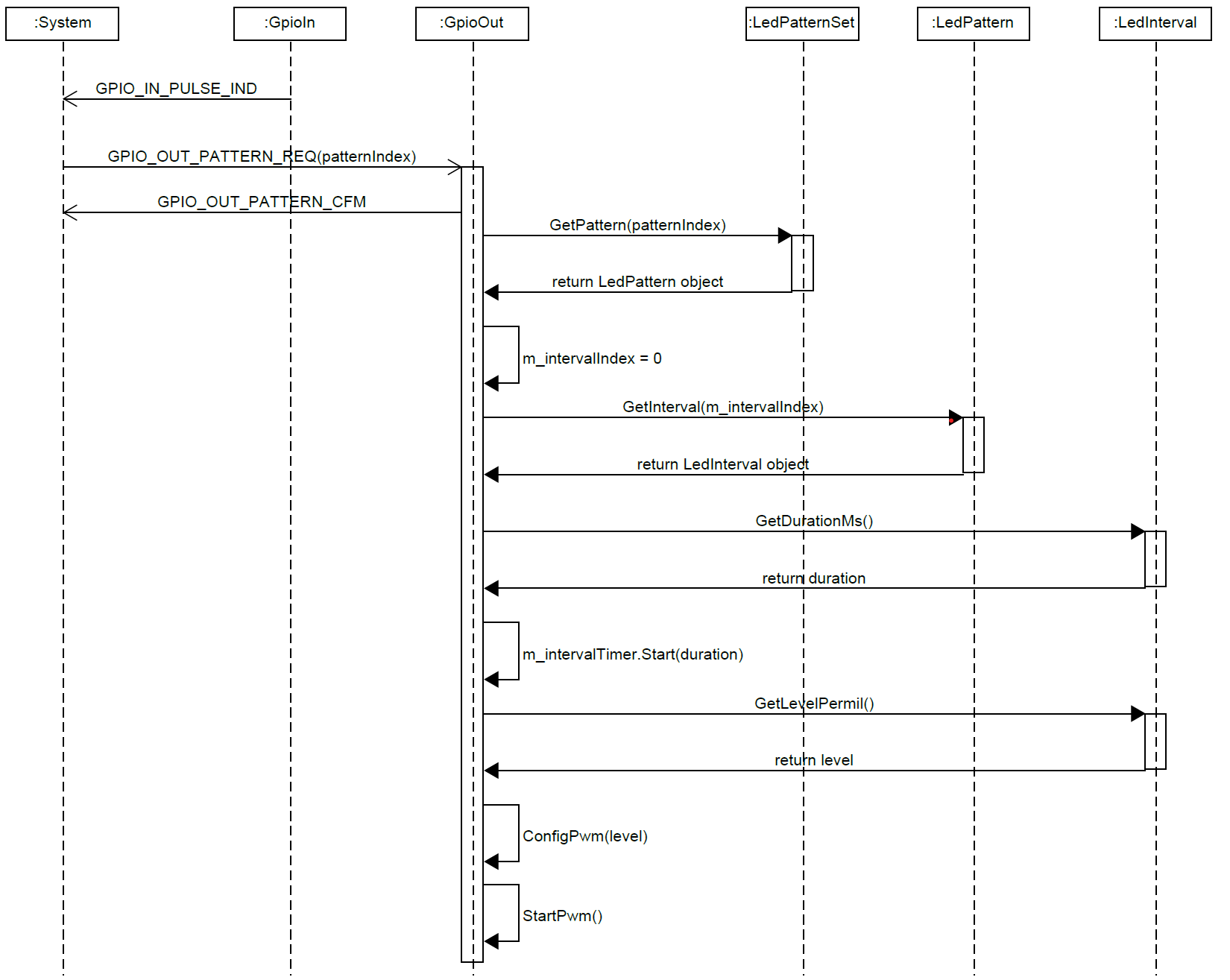
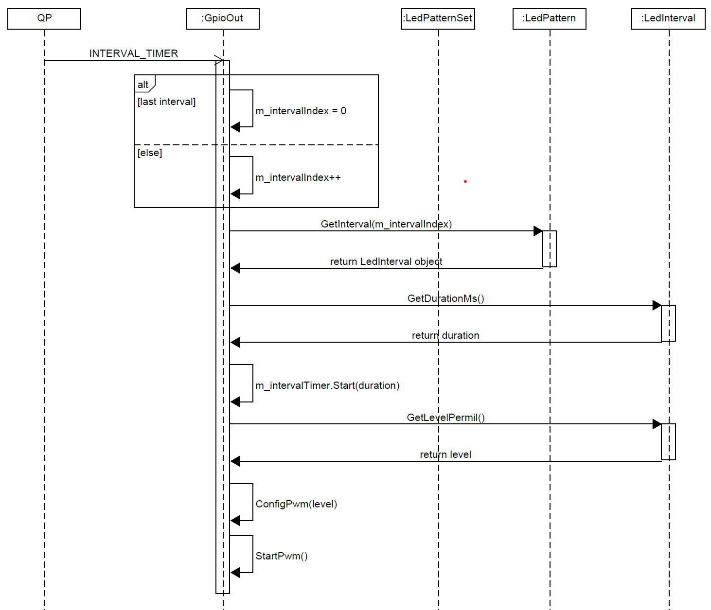
LED Pattern Generation
Back to the LED pattern example, we illustrate the interaction between a GpioOut (GPIO Output) component and the rest of the system with a couple sequence diagrams. The first diagram shows how the GpioOut object initializes an LED pattern upon a button press by a user. Note the use of both asynchronous and synchronous interactions. The second diagram shows the arrival of an INTERVAL_TIMEOUT event indicating the end of the current pattern interval. Here we use an alternative combined fragment to show two conditional paths, with one incrementing the interval index and the other wrapping it around to 0. Using timers instead sleep or delay function calls is a very common technique in asynchronous design. While waiting for the timeout event, the GpioOut object is free to handle any other events, including a new GPIO_OUT_PATTERN_REQ. It is therefore able to switch to a different LED pattern immediately even when it is waiting for the end of the current interval. In the next episode, we will show the complete statechart design of the GpioOut component.