Arch 8 – LED Pattern Statechart
In the previous episode, we presented a couple sequence diagrams showing an initialization scenario and an interval update scenario. They help us understand the high level design and interaction among components to support the LED pattern feature. However, they are only a small fraction of all possible scenarios that may happen to the component under design. To show the complete picture or model, we need another type of diagrams named statecharts.
To keep it generic, we call the component GpioOut, meaning that it is driver for a GPIO output pin. Its main function is to generate a PWM signal of which the duty-cycle varies according to a set pattern. When the pin is connected to an LED, it can be used to generate an LED pattern, such as a blinking pattern or a breathing pattern.
To many embedded software engineers, the interesting tasks are configuring the peripheral clocks, setting up the hardware timer and starting the PWM output. The main program logic is rather trivial that can be accomplished with just a few variables, for-loops and conditional statements. Indeed, figuring out how to program a microcontroller peripheral via its registers can be challenging. However, in many cases it is challenging because the interface documentation is unclear or we are just not familiarized with it, rather than the logic being complicated. In the end, all it comes down to is a sequence of register reads and writes that can be abstracted with a few function calls. The main challenge is managing the asynchronicity of a real-time system, handling all possible events in all situations with determinism.
In future episodes, we will introduce our event framework, the event naming conventions and how the GpioOut component fits into the entire system. For now, let’s focus on the statechart design of GpioOut itself.
GpioOut Statechart
This is the statechart of the GpioOut (GPIO Output) hierarchical state machine. You may open it in a new tab of your browser and zoom in to have a better view.

State Layout
Stopped and Started States
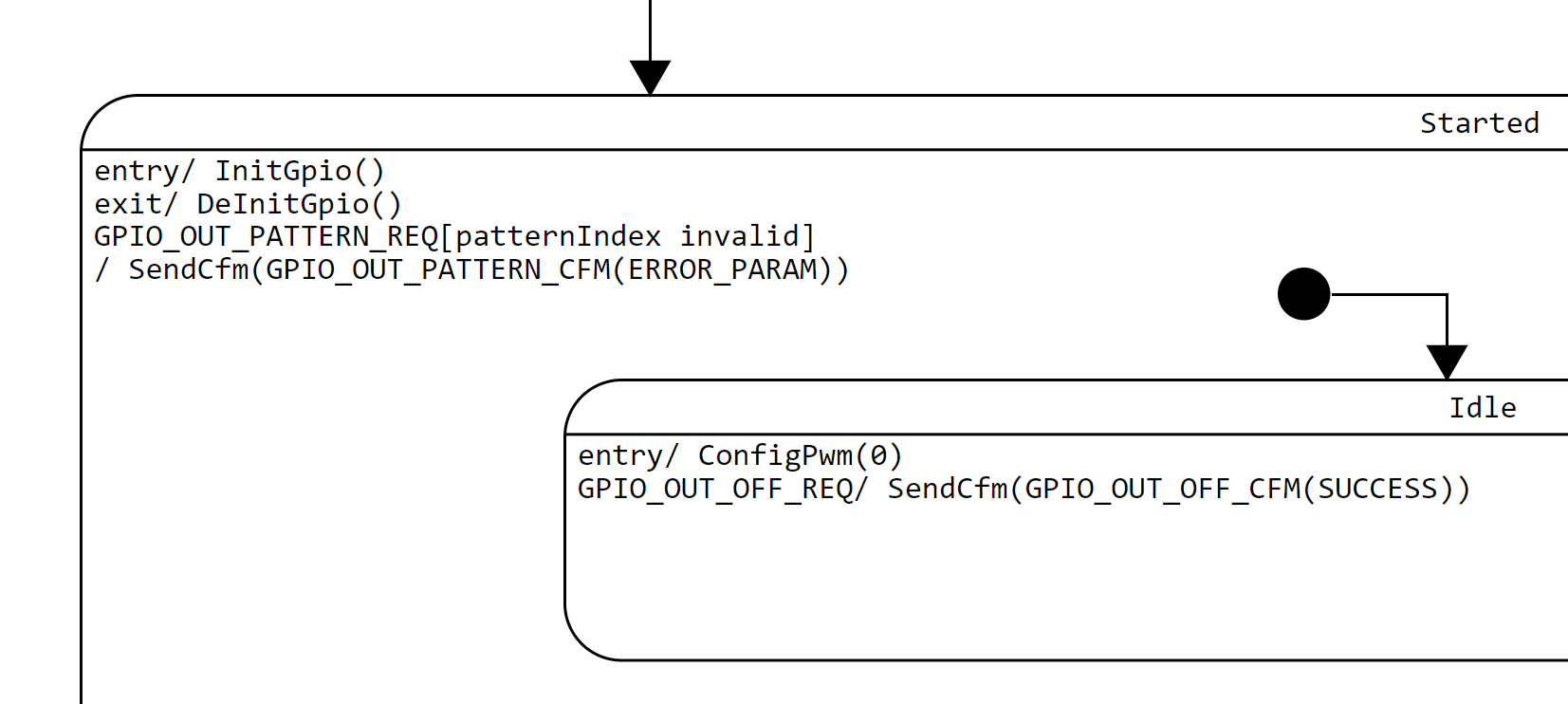
The most important aspect of a statechart design is determining the state layout or state hierarchy. As a general pattern, a hierarchical state machine (HSM) is likely to have a Stopped, Starting, Stopping and Started state at the top level. Since GpioOut is very simple, it omits the Starting and Stopping states. When it is in the Stopped state, a component is completely disabled and not functional at all. This is analogous to having a key switch on the front panel of each hardware module by which an operator can switch it on and off individually.
This is a very powerful pattern in state design. Whenever an HSM is in the Stopped state, it is guaranteed that all operations under the control of the HSM have stopped and all allocated resources are released. This includes any outstanding operations pending for completion, and any operations that are in the middle of being started or stopped. For example, in GpioOut the exit action of the Started state ensures that the GPIO pin hardware resource is released via the DeInitGpio() call.
By the same token, whenever an HSM is in the Started state, it is guaranteed that its dependencies have become ready and any necessary resources have been acquired. For GpioOut, the entry action of the Started state ensures that the GPIO pin hardware resource is initialized via the InitGpio() call.
The guarantees mentioned above are a kind of state contracts, which are naturally formed by the state definition or state abstraction. This is a distinct advantage of the statechart methodology since states and hence their contracts are formally and unambiguously defined, rather than being implicitly embedded in some combinations of variables and conditional statements scattered throughout the source code.
Nevertheless, enforcing these state contracts is often trickier than it appears. We as designers must consider all possible scenarios, including unexpected cases. Fortunately there are design patterns and heuristics to help us and we will look at some of them in future episodes.
Idle and Active States
When GpioOut is in the Started state, it is operational and is ready to be used. It does not necessarily mean it is actively showing an LED pattern. A user object can control whether it is active and which pattern it shows via the GPIO_OUT_PATTERN_REQ and GPIO_OUT_OFF_REQ. The former carries an event parameter patternIndex specifying which pattern to show, while the latter requests GpioOut to turn off the pattern. Below is an extracted portion of the Started state:
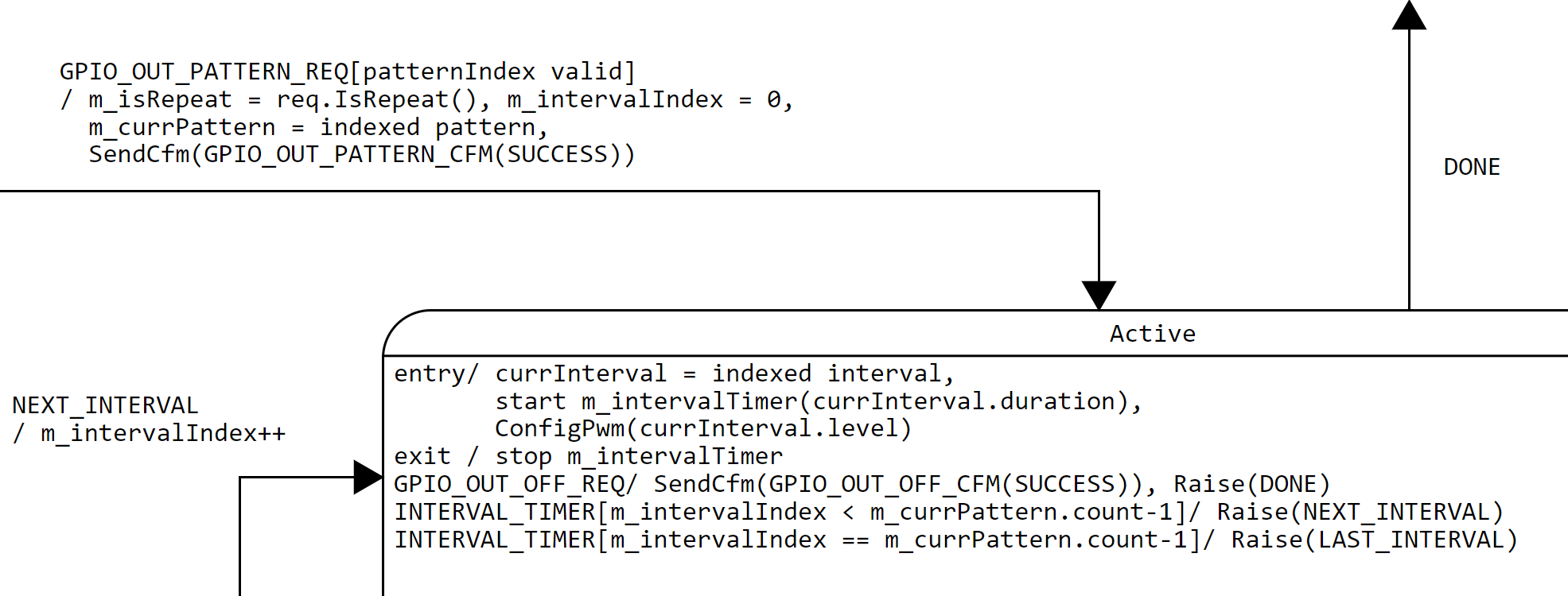
Here for the transition triggered by the event GPIO_OUT_PATTERN_REQ with the guard condition [patternIndex valid], we make use of a special kind of transition going from a superstate to a substate. We don’t find this type of transitions in a tradition FSM state diagram, and it is worth looking into the rationale behind it. What it says is that whenever GpioOut is in the Started state, upon GPIO_OUT_PATTERN_REQ with a valid patternIndex, it transitions into the Active state, no matter whether it is in the Idle or Active state. It is through this single transition that our design can instantly start a new pattern or restart the same pattern even when it is actively showing a current pattern.
The actions upon GPIO_OUT_PATTERN_REQ initialize member variables with the parameters of the requested LED pattern, such as m_isRepeat (whether it is a repeating pattern), m_intervalIndex (which interval of the pattern to show next) and m_currPattern (pointing to the requested LED pattern object). Note that m_intervalIndex is initialized to 0 since we want to start from the beginning of a pattern upon a fresh request.
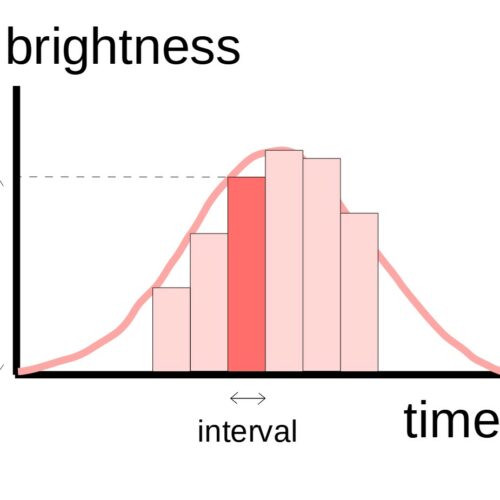
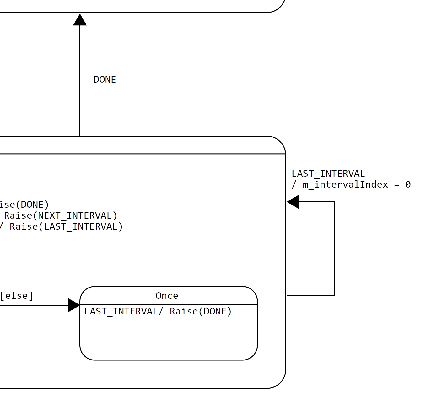
An important design choice was made to configure the PWM output (via ConfigPwm()) and start the timer (m_intervalTimer) for the current interval upon entry to the Active state. This promotes code reuse since the HSM can conveniently move on to the next interval by posting the internal event NEXT_INTERVAL or LAST_INTERVAL to itself. The only action upon these events is to update m_intervalIndex to point to either the next or the first interval (wrap-around) of the pattern. This is a common state design pattern named the reminder pattern. See Page 211 of the PSiCC book by Miro Samek (Book: Practical UML Statecharts in C/C++, 2nd Ed. (state machine.com).
You may find another example of the reminder pattern in the use of the DONE event. It factorizes the common behaviors upon a user initiated GPIO_OUT_OFF_REQ event and an internally generated LAST_INTERVAL event for a non-repeating pattern, which cause the HSM to transition to the Idle state. For the former, it additionally sends a confirmation event (GPIO_OUT_OFF_CFM) to the requesting component.
Using statecharts, we achieve code reuse (factorization) at the design level rather than at the coding level. It allows us to see the high-level logic in an overall picture (literally) rather than the low-level variable manipulation (set/clear/test) across many functions. A clean design naturally leads to clean code.
Repeating and Once States
The Active state is further partitioned into the substates of Repeating and Once. They represent two different modes of operation, namely repeating and non-repeating patterns. It enters one of these states via the initial transition of the Active state based on the member variable m_isRepeat. Recall that m_isRepeat was initialized with an event parameter of GPIO_OUT_PATTERN_REQ.
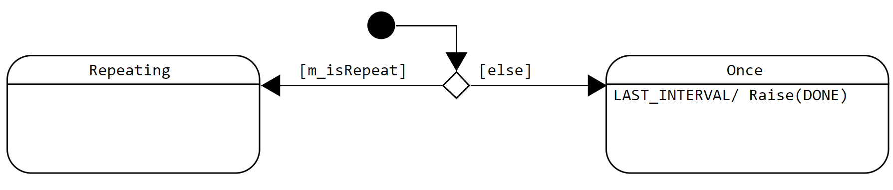
Here is an interesting observation – the Repeating state is empty! One may wonder why we would need a state which does nothing. For traditional FSM, this may point to a bad design (a dead state), but for HSM this is a very useful technique. The Repeating state and Once state differ in the way they handle the end of a pattern. Upon the LAST_INTERVAL event, the Repeating state restarts from the beginning of the pattern, whereas the Once state turns off the pattern.
By doing nothing, the Repeating state simply lets its superstate Active handle the LAST_INTERVAL event, which resets m_intervalIndex to 0 followed by a self-transition. On the other hand, the Once state overrides the handling of LAST_INTERVAL in its superstate by posting an internal event DONE, which is immediately processed by the HSM to transition from the Active state to the Idle state. The entry action of the Idle state guarantees that the LED is turned off as a state contract. Here we use the term “raise” to refer to the action of posting an internal event to itself (see SCXML). We will discuss different types of events and queues in future episodes.
Exception Cases
The graphical nature of statecharts helps expose hard-to-find exception cases which would otherwise be hidden until testing or deployment.
One example is the GPIO_OUT_PATTERN_REQ event carrying an invalid parameter, namely an invalid pattern index. We use guard conditions to ensure both the normal and exception cases are handled. In either case, it ensures a matching confirmation event (success or failure) is replied back to the user component. The following extraction shows the handling of this exception case.
Let’s Run It
With the statechart design done, we may now code it up. An example implementation using QP for the STM32L4S5 IoT Discovery board (B-L4S5I-IOT01A) can be found at our project repository at GitHub.
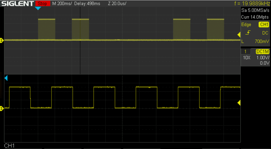
This is the console log showing one cycle of Pattern 1 – two short blinks, defined as:
// Pattern 1
{4,
    {
        {500,200}, {0, 200}, {500, 200}, {0, 1000}      // two short blinks.
    }
}
which consists of two pulses at 50% intensity each with a duration of 200ms. The oscilloscope captures below show the PWM signal at the GPIO pin driving the onboard USER LED (PB.14). The first one is a zoom-out capture showing two cycles of the pattern, each consisting of two blinks. The second one zooms in to show the PWM waveform with a 50% duty-cycle.
13946 USER_LED(35): Active ENTRY
13946 USER_LED(35): Repeating ENTRY
14146 USER_LED(35): Active INTERVAL_TIMER
14146 USER_LED(35): Active NEXT_INTERVAL from USER_LED(35) seq=24
14146 USER_LED(35): Repeating EXIT
14146 USER_LED(35): Active EXIT
14146 USER_LED(35): Active ENTRY
14146 USER_LED(35): Repeating ENTRY
14346 USER_LED(35): Active INTERVAL_TIMER
14346 USER_LED(35): Active NEXT_INTERVAL from USER_LED(35) seq=25
14346 USER_LED(35): Repeating EXIT
14346 USER_LED(35): Active EXIT
14346 USER_LED(35): Active ENTRY
14346 USER_LED(35): Repeating ENTRY
14546 USER_LED(35): Active INTERVAL_TIMER
14546 USER_LED(35): Active NEXT_INTERVAL from USER_LED(35) seq=26
14546 USER_LED(35): Repeating EXIT
14546 USER_LED(35): Active EXIT
14546 USER_LED(35): Active ENTRY
14546 USER_LED(35): Repeating ENTRY
15546 USER_LED(35): Active INTERVAL_TIMER
15546 USER_LED(35): Active LAST_INTERVAL from USER_LED(35) seq=27
15546 USER_LED(35): Repeating EXIT
15546 USER_LED(35): Active EXIT
15546 USER_LED(35): Active ENTRY
15546 USER_LED(35): Repeating ENTRY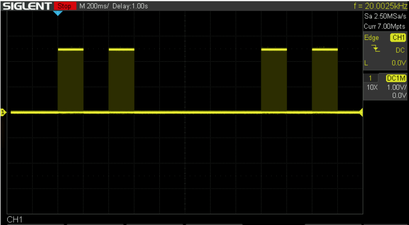
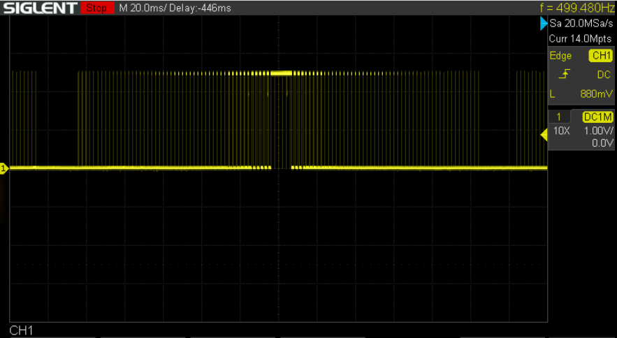
This is another pattern with the LED intensity ramping up and down exponentially. Each interval lasts for just 10ms. The PWM frequency has been lowered from 20kHz to 500Hz to make the pattern visible in the oscilloscope capture below. Next time when you blink an LED in your product, try to add this ramping or breathing effect. It may add a sense of sophistication and make it stand out from its competitors!
// Pattern 0
{23,
    {
        {0, 10}, {1,10}, {2,10}, {4,10}, {8,10}, {16,10}, // Ramps up.
        {32,10}, {64,10}, {128,10}, {256,10}, {512, 10},
        {999, 10},                                        // Max.
        {512, 10}, {256,10}, {128,10}, {64,10}, {32,10},  // Ramps down.
        {16,10}, {8,10}, {4,10}, {2,10}, {1,10}, {0, 10}
    }
},
Appendix – The Not So Interesting Code
As mentioned above, programming the microcontroller peripherals can be challenging but in fact it is nothing more than a sequence of register reads/writes. This is the ConfigPwm() source code in case you are curious how it looks like:
void GpioOut::ConfigPwm(uint32_t levelPermil) {
    FW_ASSERT(levelPermil <= 1000);
    if (!m_config->activeHigh) {
        levelPermil = 1000 - levelPermil;
    }
    // Base PWM timer has been initialized by System via Periph.
    TIM_HandleTypeDef *hal = Periph::GetHal(m_config->pwmTimer);
    StopPwm(hal);
    TIM_OC_InitTypeDef timConfig;
    memset(&timConfig, 0, sizeof(timConfig));
    timConfig.OCMode       = TIM_OCMODE_PWM1;
    timConfig.OCPolarity   = TIM_OCPOLARITY_HIGH;
    timConfig.OCFastMode   = TIM_OCFAST_DISABLE;
    timConfig.OCNPolarity  = TIM_OCNPOLARITY_HIGH;
    timConfig.OCNIdleState = TIM_OCNIDLESTATE_RESET;
    timConfig.OCIdleState  = TIM_OCIDLESTATE_RESET;
    timConfig.Pulse        = (hal->Init.Period + 1) * levelPermil / 1000;
    QF_CRIT_STAT_TYPE crit;
    QF_CRIT_ENTRY(crit);
    HAL_StatusTypeDef status = HAL_TIM_PWM_ConfigChannel(hal, &timConfig,
        m_config->pwmChannel);
    FW_ASSERT(status== HAL_OK);
    StartPwm(hal);
    QF_CRIT_EXIT(crit);
}