LED Panel 4 – LED Panel Design with Statecharts
Having seen the hardware interface to the RGB LED panels, we shall now look at how we can control them with software. To start, let’s recap the timing diagram introduced in the last episode:
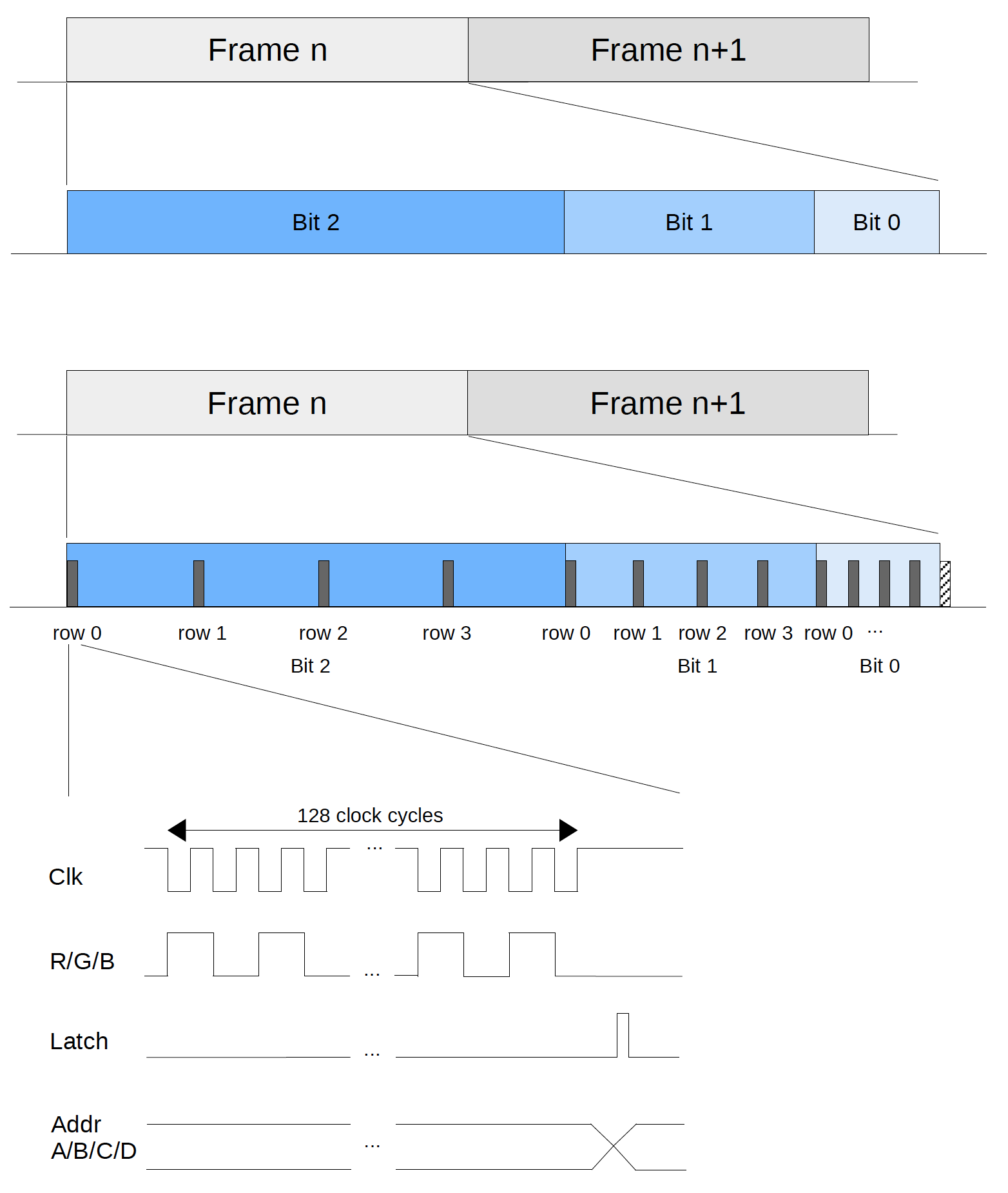
It uses binary code modulation (BCM) in which software repeatedly clocks out R/G/B data in intervals of geometrically increasing durations. Timing control is the most critical here, as the generated color depends on individual R/G/B light intensity which is in turn proportional to the on/off time controlled by BCM interval durations. This is a typical real-time system in which time plays an important role in the desired function of the system. If timing is off, colors won’t look right and images may flicker. Nonetheless, for its intended purposes the outcome is not catastrophic, and therefore we call it a soft real-time system as opposed to a hard real-time system.
One common way to control timing is to use a sleep(), wait() or delay() function. Depending on whether you are running a bare-metal or an RTOS-based system, such function either uses a while-loop to check when the system tick counter exceeds an expiration value, or performs a task-switch (i.e. blocks) until the timeout period has expired. In any case, your current control thread becomes unresponsive while waiting, not to mention that the while-loop approach consumes unnecessary power.
It is better to use an interrupt-driven approach with a HW peripheral timer provided by a microcontroller (MCU), which is an STM32H743 chosen for this project. At timeout, the MCU generates a timer interrupt triggering an interrupt-service-routine (ISR) to run. It is then up to the software to decide what to do in the ISR. Does this sound familiar to the event-driven approach we have been looking at in the Microbit episodes? Again, state is an essential concept here: What the software does (actions) upon an interrupt (event) depends on the current position in the timing sequence (state).
Let’s analyze our problem in hand using a simple system of 1:4 scan rate and 3-bit color depth. In practice our LED panels are of 1:16 scan rate with at least 6-bit color depth. This is simplified in this analysis for illustration. The diagram below shows one complete frame:
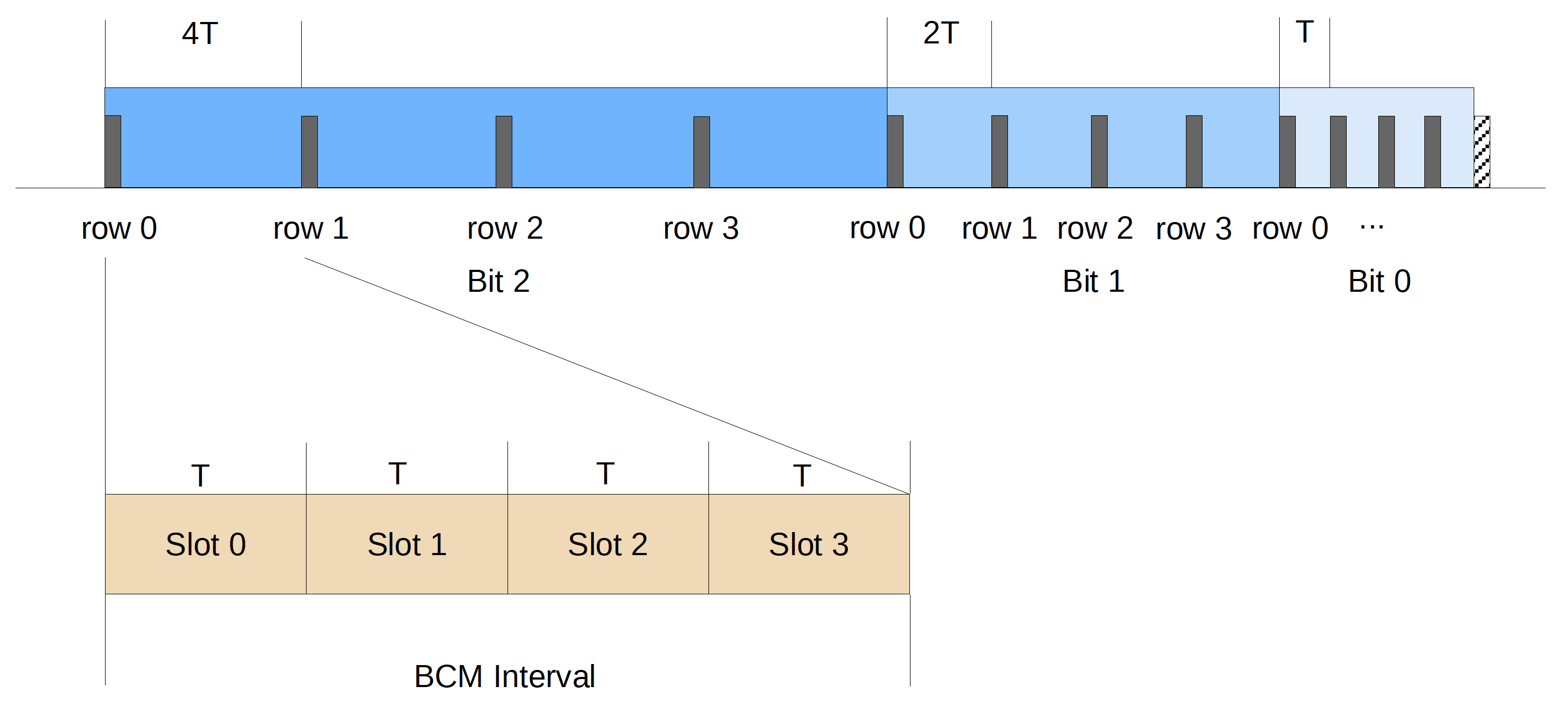
Each time, the MCU clocks out the RGB color data (shown as grey bars) to a single row of LEDs. After waiting for a certain interval, called the BCM interval, it repeats for the next row until all rows have been scanned. Then it moves on to the next color bit either in ascending order (i.e. increasing from the least significant bit) or descending order as shown.
The color data are clocked out using the TIM (Timer) and DMA (Direct Memory Access) peripherals of the STM32 MCU. The hardware timer generates a clock signal using PWM while DMA outputs the color data from memory to a GPIO port at each falling edge of the clock. Getting the hardware to work properly can sometimes be tricky, but in the end it is just a sequence of registers to program to the MCU which can be wrapped up in some functions. What is more challenging is to precisely control the timing between each time these clock and data are generated, which is labeled as BCM interval in the diagram above.
We notice that BCM intervals are always multiples of T. We call this shortest interval T a slot. More precisely the interval for color bit i, Ti, is equal to 2i x T, and therefore we can view each BCM interval as containing 2i slots. To wait for a BCM interval, the software can start a periodic timer (called slot timer) with a timeout period of T and count for the number of interrupts or slots occurred. This approach is simple since it uses a fixed timer instead of constantly restarting a timer with different timeout periods. It also extends well to drive multiple LED panels in parallel.
Once we have identified events (slot timer interrupts), we need to determine states. This is more challenging since states are abstract and can be hard to grasp. Luckily there are a few heuristics that can help us with the task. The most important concept of state design is abstraction. We need to abstract away unimportant or irrelevant details, leaving behind situations that we care about and those are what we call states.
Going back to our LED control algorithm, we recognize the critical element is to keep track of BCM intervals (Ti = 2i x T) by counting the number of slots occurred from the beginning of an interval. In software we can easily maintain the slot position with a variable named slotIdx, ranging from 0 for the first slot to 2i – 1 for the last slot (e.g. 3 in our example). In other words, there are 2i different values that can possibly be assigned to slotIdx. Are all of them relevant to our design?
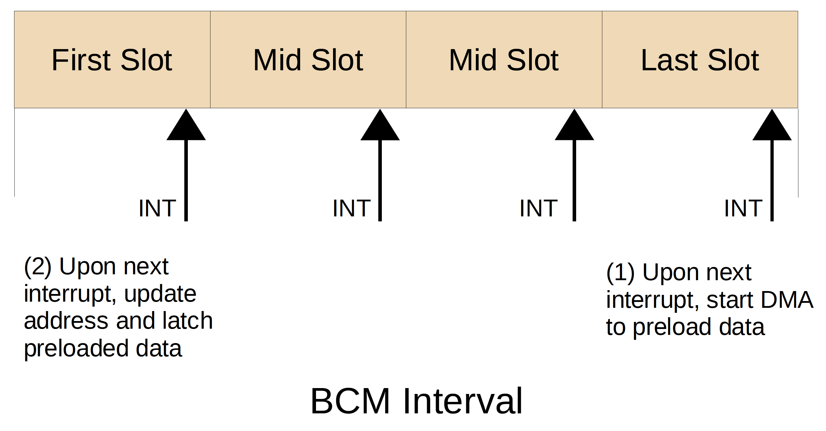
As shown in the interval above, the driver initiates a DMA transfer in the last slot to preload the shift register for the next interval. Later in the first slot, the driver updates the row address and latch the preloaded data to the selected row of LEDs. All it cares about are the first and last slots. Those that lie in between are irrelevant and can simply be abstracted away as mid slots.
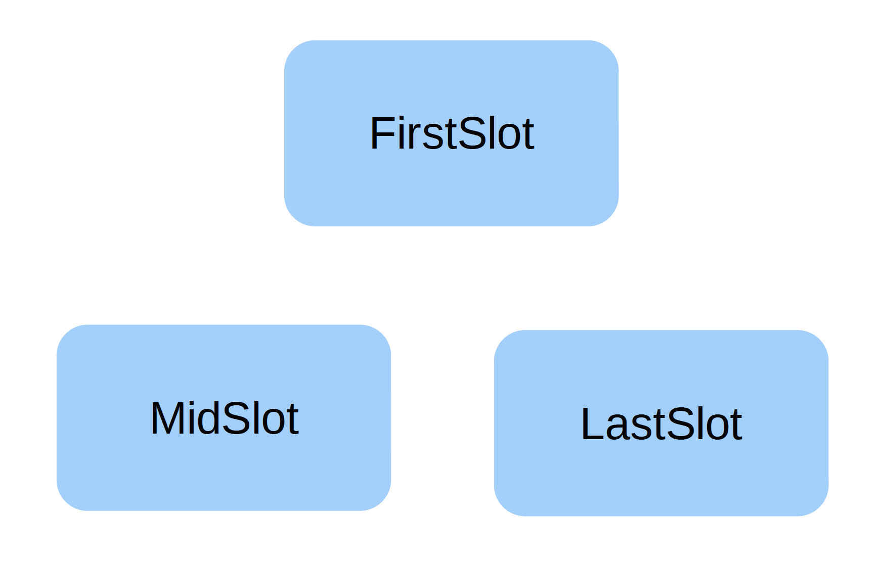
Bingo! We have just come up with the three main states of our algorithm, namely FirstSlot, MidSlot, LastSlot states.
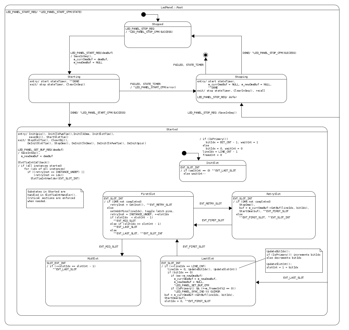
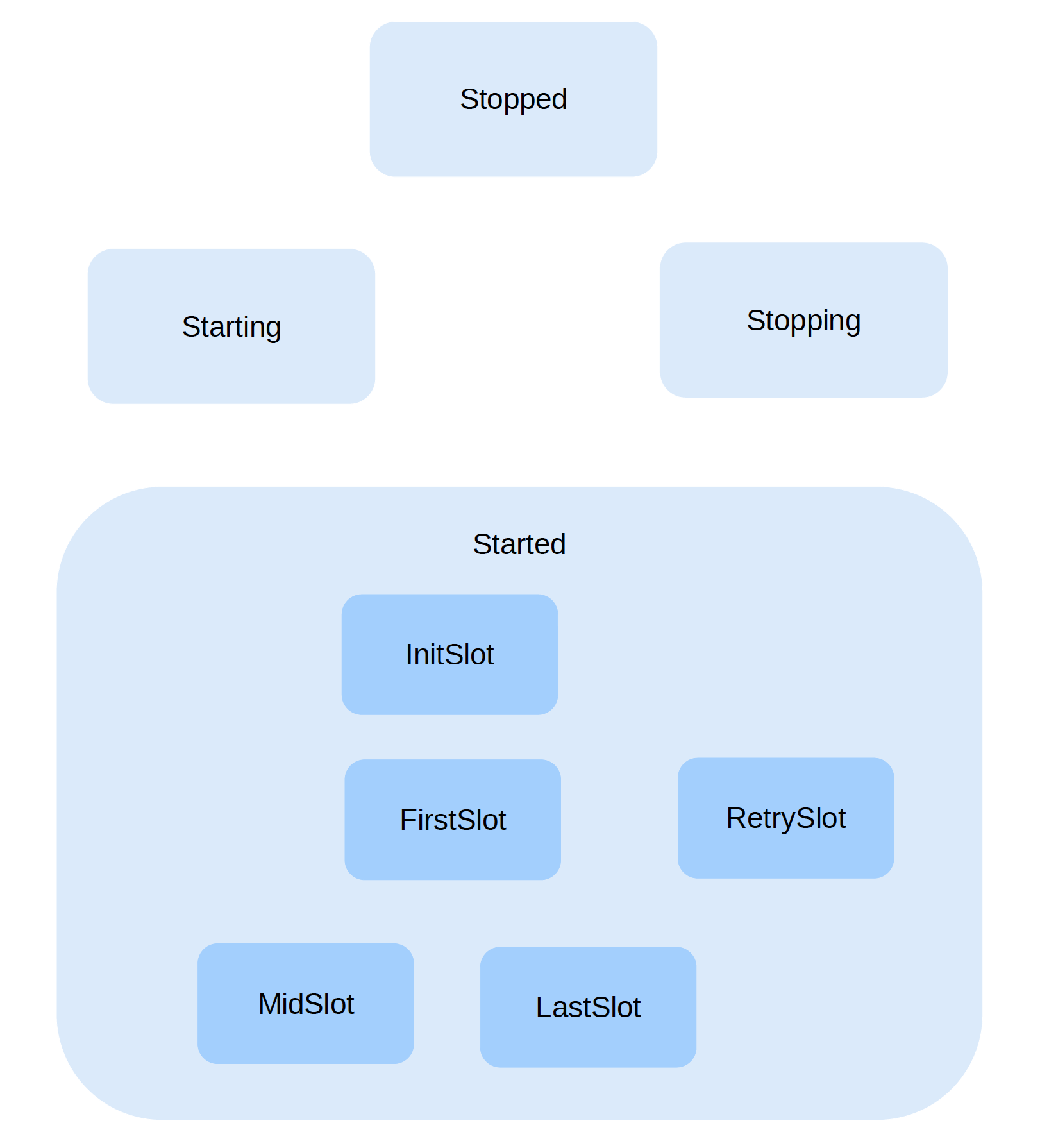
As we shall see later, DMA might occasionally miss its deadline (due to bus contention). In order to recover from these rare events gracefully, we add a RetrySlot state. To support a larger display, we will run two instances of the driver concurrently. To optimize bus utilization, we add an InitSlot state to insert some delay or offset between the timing of the two instances. To allow the driver to be cleanly disabled and enabled, we add a Stopped state and a Started state, with the intermediate Starting and Stopping states. We group all the 5 slot states as substates under the Started state. With these, our initial statechart has evolved to:
Adding details of events, actions and transitions, we have come to the complete statechart that specifies all the behaviors of our LED panel driver. We call this driver the LedPanel active object. In the next episode, we will explore how to implement this statechart directly in an ISR using C++ while meeting stringent real-time requirements in the microsecond order.
