ST 9 An Objected-oriented Architecture for Embedded Systems
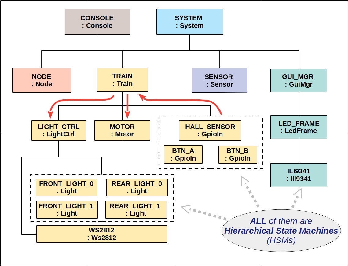
This is the object diagram showing the main software components, or objects, of this G-scale model train. For embedded systems, an object-oriented architecture is very useful in encapsulating hardware resources.
To a microcontroller, no matter it is a push button or a hall-effect sensor, they all appear as GPIO input pins. It makes sense to encapsulate the configuration, interrupt detection and level tracking of each pin into a class named GpioIn (meaning GPIO Input). We can then instantiate one GpioIn object per pin used in the system.
For example, we have two objects named BTN_A and BTN_B for the two buttons, and one object named HALL_SENSOR for the hall-effect sensor. These object names are C++ enumerations uniquely identifying each object in the event framework. Later, we can even use GpioIn to support data-ready interrupts from IMU and environmental sensors!
On the output side, we have a class named Ws2812 handling the 2-wire bus interface to an RGB LED stripe. Since we chain the two front lights and two taillights together, we only need one Ws2812 object (conveniently named as WS2812).
Above WS2812, we have four Light objects (e.g. FRONT_LIGHT_0, etc) each controlling the behaviors of a single LED. Upon request, each Light object can display an arbitrary color pattern or transitions to a new color. All these Light objects rely on a common Ws2812 object to update colors on the LED strip. At a higher level, we have a LightCtrl object to ensure the front lights and taillights are perfectly coordinated according to the current operation of the model train.
As we go up the hierarchy, we can see the goals of a component become more abstract and strategic. For the LED example, it goes from managing bits and clock, to colors and patterns, and finally to lighting control pertaining to the overall train operation.
